Electrical system
For mobile
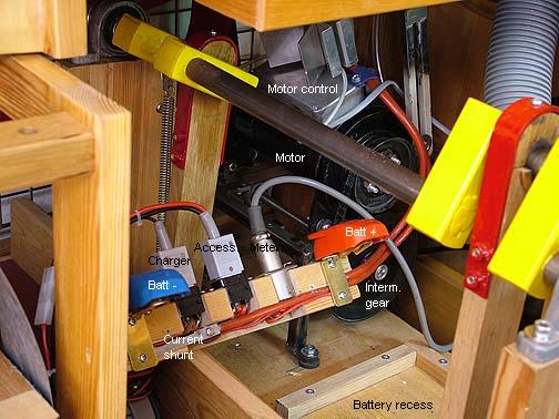
use the system is powered from a standard 80 Ah, 12V lead battery. This
is enough for playing 3-4 hours. The battery is placed under the feeder
crankshaft. This photo shows its immediate environment when the battery
is removed. Connections are concentrated to a clip-on contact bar, here
less a protective cover. The bar holds contacts for remote meters for
voltage and current, for an 'intelligent' battery charger, and for
accessories. Apart from the chest magnets these accessories
include the MIDI diskette reader and the master keyboard. These are
originally equipped with 220 VAC adaptors. At present they are powered
via an inverter from 12 VDC into that mains voltage, an obvious area
for future rationalization.
In the background of this photo you see the feeder drive motor with its
control box and its intermediate gear shaft. These are mounted on a
cradle, pivoting around rubber washers, one of them seen below the
contact bar. The belt connecting the intermediate shaft to the
crankshaft is tensioned by a spring, hardly visible below the
intermediate gear wheel.
|
 |
The meters
for voltage and current are located up on the right pillar for easy
reading. Their ranges are modified to suit the application.
|
 |
Motor drive regulator
In normal free standing use air is
supplied by the bellows, powered
from a battery driven motor. This motor is an old style 12VDC car
generator, slightly modified. The speed of this motor is controlled
such that the air reservoir lid is held at an intermediate position,
sensed by a linear potentiometer, R8 in this diagram.
A1 is an
oscillator, astable multivibrator. Its hysteresis is controlled by the
positive feedback network R1-3 and its frequency by R5-C1, with the
elements shown about 8 kHz. In A2 the sawtooth at C1 is compared to the
voltage of the bellows sensing potentiometer R8. This results in a
pulse width modulation signal at A2 output pin 1. I had to insert an
emitter follower Q1 for sufficiently fast drive to the power FET Q2.
When everything is turned on by switch S1 and relay S2, the slow
charging of capacitor C2 implements in a raw and simple way a smooth
acceleration of the motor, no overly big start current. I did
unsuccessfully try some ways to make an over current cutout by sensing
the drop over the fuse F. Skipped that after all, did not seem too
necessary. The fuse remains from earlier versions, but I doubt it is
very meaningful. |
 |
I modified the car generator somewhat,
insulating its
second brush from the grounded case. Also swapped to connect that one
to the 'DF' terminal rather than the field winding, instead field was
connected to the case. The terminal denominations in the diagram are
after modification - the original generator was not internally
connected the way shown.
The pulse width modulation of the
supply to the rotor controls the average
voltage across it (between
D+ and DF) to be from essentially zero up to the battery voltage. This
voltage is about proportional to the motor speed, in turn connected to
airflow delivered. On the other hand the average current through the rotor
is in proportion to the torque delivered, and this torque is
essentially constant since pressure in the driven bellows is
independent of how much air is consumed. But this current is drawn from
the battery only at the open part of the duty cycle, when Q2 is turned
on. With Q2 off the same current flows in the rotor (due to the
inertial effect of its inductance) with a return path though the
'freewheel diode' D1. The result is that the average current and power
drawn from the battery is proportional to air usage, despite the fact
that motor current is constant.
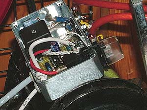
This photo
shows my
endeavors to cram everything into a small metal box, riding piggyback
on the motor. It remains a bit awkward to me how to unite such
miniature
electronic circuits with the high current power ones, connected with
nuts and bolts rather than tiny solders. The power semiconductors D1
and Q2 are mounted on insulating washers inside the box, using the same
bolts as for the middle two external connections.
Q2 fused a couple of months after this photo. The replacement was
mounted on a big external heatsink seen in the top photo of this
section.
|
 |
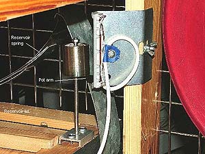 |
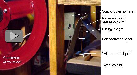
The
control potentiometer R8 is a linear one made for mixer consoles. I
connected its two 10 kohm stereo runs in parallel to have a 5 kohm pot
with possibly less noise. The picture shows the rig with the
reservoir bellows lid in empty position. In the lower half of the lid
travel
the pot arm is held in its bottom position (for full motor speed) by a
weight sliding on the vertical guide pin. The upper half of its travel
the lid pushes the pot up over a 60 mm range.
|
The 8 kHz magnetostriction whine from
the motor is faintly audible but
does not disturb the music. I prefer to keep it for a while, just as an
operator's check that everything works as it should. Later I might
reduce C1 to make it supersonic.
One feature of the connections layout is that if (or when?) the
electronics break down, then I can move the motor DF cable to the
adjacent B- terminal and let the motor go at full speed all the time.
Then it is up to the old
proven reservoir valve regulation to take over, though more noisy and
jerky.
Practically, this setup works fine. The battery consumption is about
13A, rising to some 17A when playing loud. Some power saving, but not
very significant. The assembly becomes a bit hot, some 65 deg C, at
continuous use. As far as I can judge the heat comes from the motor
rather than the electronics.
Using this speed regulation there is now much less rumble from the
bellows when the organ idles,
because of reduced speed, crankshaft only at about 20 rpm. Full speed
45 rpm
is reached momentarily at loud passages. This is a very pleasing
improvement, the one making the speed regulator adventure really
worthwhile.
Here
is a video recording (15 MB) seen from the opposite side. It shows how
the reservoir is rapidly filled when the motor is started. Since the
soundtrack has automatic gain control the background noises and bellows
squeaking are prominent. After a few seconds music starts vigorously
such that the reservoir lid dives, but the regulating system catches up
fast. It is difficult to perceive that the drive wheel speed varies a
lot.
|
|
 |