There is a wide variety of tuned percussion instruments used as pipe organ ranks, from the harsh ring of the glockenspiel or metallophone, through the magisterial tone of the tubular chime, to the "bonk" of the wooden xylophone. There is even more variety in the names used for these ranks, depending on which national organ tradition, in which one is speaking. So describing the sound of these "chimes" by name is difficult.
This article describes a harp (glockenspiel, celesta, metallophone, lyre, chimes, or whatever you would name it) that I developed in the first half of 2002 for my street organ. It outlines some theoretical principles for its sounding bodies and beater mechanisms and shows how these were finally implemented. The tone in the present device is a rather pure sinusoidal note, with some initial 'clang' at the attack, and a long, firm sustain. They sound rather like the Harp rank included in American residence organs, or the Mustel Celeste rank found in many French reed organs.
The closest material from European makers is 25 mm square with only
2 mm wall thickness. From such I copied Rossing's fork. Since the
original
is more solid I expected mine should have slightly shorter tines. But
to
my surprise dimensions came out the same to within a mm - obviously the
tine skirts dominate the stiffness. To the eye the forks look
identical,
except for that wall thickness.
Fig 1. Dimensions of my copy of Rossing's fork.
The working principle is as follows. The tube is slotted on both sides, from one end to form a tuning fork. Here material, profile, and length of the tines determine what will be the fundamental frequency when you strike it. In the fundamental mode the tines swing in opposite directions to each other and the unslotted remaining handle part of the tube is basically immobile. This means that it does not really matter how you hold it, the support largely does not affect the oscillation. In case the fork tines are slightly asymmetrical, it does not mean the fork will deliver two tones. Instead the handle will oscillate somewhat. The consequence is then that the fork Q value decreases, the tone will die out faster.
A tuning fork is a particularly inefficient sound radiator at its fundamental frequency. Basically a quadrupole - the tine insides form two sound (monopole) sources while their outsides form two symmetrically located sources of opposite sign. All these sources are closely located in terms of sound wavelength, so the their emitted sounds largely cancel.
A key means to raise the totally radiated sound power is to tune the interior of the handle. One way is to make it a quarter wavelength resonator, closed at its far end. This will then absorb most of the sound generated inside between the tines. So what is left acoustically is the outsides of the tines working together as a monopole sound source, much more efficient than the quadrupole. A different way is to make the handle a half wavelength resonator, open at its far end. Then the sound from the insides of the tines is effectively transported to the other end of the resonator tube where it appears in opposite phase. The externally audible result is then two in-phase sources (tine outsides and handle end), located about a half wavelength apart. Because of this distance these moreover mutually enhance in the equatorial plane of the tube, giving a reason to place the tubes upright, just like ordinary open flue pipes. I adopted the latter method, which is somewhat superior in loudness. This makes for longer handles, but puts no big space problem since the frequency range considered is fairly high.
At striking such a fork a complex inharmonic spectrum is produced initially. Many inharmonic modes, both longitudinal and lateral, higher than the fundamental are excited, but these die out quickly as they tend to shake the handle and are absorbed. What remains later is a clean, sinusoidal tone. The striker hardness is selected to evoke a sensible amount of these higher modes which define much of the tonal character. This timbre differs depending on wall thickness. Between the original and copy forks there is an audible difference in the clang at the blow, but I fail to rank them in preference. With both forks the long lasting fundamental Q value is about 5000. In the actual frequency range this corresponds to a 60 dB decay time about 10-15 seconds, about twice what I get with similar forks made from steel. (For the topic of Q value, you may refer to http://mmd.foxtail.com/Tech/qval.htm).
Fig 2. Spectra immediately after hitting Rossing's fork and my thin walled copy of it. Frequency range is 4 kHz, time window 0.1 s, and vertical scale is in dB with an arbitrary reference level. Click image to hear them.
One issue is what absolute dimensions to use, an analogy to scaling pipes. In a pipe resonator frequency F is proportional to F = (const) / R where R is its length and the constant accounts for general shape and speed of sound. Here the width scale has little to do with frequency, this instead affects loudness, timbre, etc. - Solving the formula you find the resonator length R to be inversely proportional to frequency. The usual organ pipe modifications apply, you have to account for end corrections.
In a bar (e.g. fork tine) the fundamental resonance frequency obeys the dissimilar proportionality F = (const)* D / T2 where D is thickness, and T is length. The constant includes other factors like Young's modulus, density, profile shape, taken to be the same at all scales. The fundamental is essentially independent of width. However, if you want to preserve the relations between fundamental and higher modes you have to scale W the same as T and D. This is a rule that is hardly practical because of limitations in available material supply dimensions. - Solving the formula holding D constant you find the tine length T to be inversely proportional to the square root of frequency. Another way to state the same thing is to say the 'halving number' is 24. That is, shortening the tines into half as long, frequency will rise 24 semitones, or two octaves.
With the 25 mm square aluminum tubes I found the following empirical formulas for T and R of fig 1, for frequency F Hz::
| MIDI # | Note | Frequency | Wavelength/2 | Tine length | Res. length | Total length |
| F (Hz) | l/2 (mm) | T (mm) | R (mm) | Ltot (mm) | ||
| 72 | c'' | 523 | 327 | 95.2 | 304 | 399 |
| 73 | c#'' | 554 | 308 | 92.5 | 286 | 378 |
| 74 | d'' | 587 | 291 | 89.8 | 268 | 358 |
| 75 | d#'' | 622 | 275 | 87.3 | 252 | 339 |
| 76 | e'' | 659 | 259 | 84.8 | 237 | 321 |
| 77 | f'' | 698 | 245 | 82.4 | 222 | 305 |
| 78 | f#'' | 740 | 231 | 80.0 | 208 | 288 |
| 79 | g'' | 784 | 218 | 77.8 | 195 | 273 |
| 80 | g#'' | 831 | 206 | 75.6 | 183 | 259 |
| 81 | a'' | 880 | 194 | 73.4 | 172 | 245 |
| 82 | a#'' | 932 | 183 | 71.3 | 161 | 232 |
| 83 | b'' | 988 | 173 | 69.3 | 150 | 220 |
| 84 | c''' | 1047 | 163 | 67.3 | 141 | 208 |
| 85 | c#''' | 1109 | 154 | 65.4 | 132 | 197 |
| 86 | d''' | 1175 | 146 | 63.5 | 123 | 186 |
| 87 | d#''' | 1245 | 137 | 61.7 | 115 | 176 |
| 88 | e''' | 1319 | 130 | 60.0 | 107 | 167 |
| 89 | f''' | 1397 | 122 | 58.3 | 100 | 158 |
| 90 | f#''' | 1480 | 116 | 56.6 | 93 | 149 |
| 91 | g''' | 1568 | 109 | 55.0 | 86 | 141 |
Table 1. Computed fork dimensions for my implemented tonal range. These figures match the finally tuned values, mostly within one millimeter.
For space reasons I chose to make a set of 20 notes, divided into two sets of 10. My original plan was to spread those over two octaves, g' - g''', omitting most of the sharps. Early experiments showed that the lowest half octave in this range gave rather low sound level, and it did not improve significantly by increasing tube dimension to 30 mm square, still with that 2 mm wall. It appears that a thicker wall is essential to extend range gracefully toward lower frequencies. Because of such material supply deficiency, and also following trial music arrangements which hinted that a chromatic scale was very desirable, my plans were modified to use the reduced range of Table 1.
To fabricate the forks I drilled a 9 mm hole through the tube and coarse cut the slot with a band saw. Then trimmed the slot by milling it to the final 7 mm tine flange thickness to a tolerance about 0.1 mm. This is also feasible by hand filing.
It is straight forward to tune the tines to within a cent or two with a stroboscopic tuner. You file off the tine tips to elevate frequency, or file down the slit bottom to lower it. The final adjustments are quite small and can be done by scraping.
Having tuned the tines, you can get a coarse indication on how the resonator matches by listening to the noise when blowing across the slot. It appears to me the tube resonance should be within some 10 to 15 ct before its action deteriorates, so that method alone is not accurate enough. If you use a closed tube resonator it is easy to search for an optimal position of a movable stopper. Open resonator tuning would also be, should you equip the open end with a sliding door or a sleeve like in ordinary organ pipes. But as I wanted open resonators with fixed tuning it became a good deal more tricky. I settled for a couple of earphones near outside the bottom of the slot, driven from a tone generator. Then picked up the sound near the open end with a miniature microphone. This allowed me to determine what was the resonance from an oscilloscope displaying the generator drive and the microphone signals as a Lissajous figure. After adjusting the generator to find the resonance you use the tuner to measure its deviation from the ideal. Finally you can trim the tube length, knowing that shortening the resonator by 1% will raise the resonance frequency some 17 ct. Hopefully you will have to raise it, otherwise the tube is already too short. So it is wise to add a small margin when cutting the blanks.
An optimal striking point is some 15 to 25 mm from the end of a tine, not very critical. In the lowest fork I made (g', later abandoned) the initial sound was slightly more agreeable striking about mid-way between tine tip and slot bottom - this would minimize excitation of a higher mode having a node about there.
Also, and in particular if you make the fork from a round tube, it
is
fairly important you strike the tine sideways centrally, not to the
side
near the slot. If you do, the fundamental is much weaker excited, and
also
you evoke a mode where the tines twist along their axes, inefficient
sound
radiation. This mode has a lower frequency than the wanted fundamental,
inharmonic of course.
For the drive, my wedge pneumatic has a lid area S=30*100 mm, d=10 mm gap at its opening end, 5 mm at its center (for the working part of its throw). With a blowing pressure P=3 kPa (12 inWC) it nominally develops a force at its middle F=P*S=3000*0.03*0.1=9 N (2 lb), and energy E=F*d/2=9*0.005=45 mJ.
For the hammer head, the intermediate energy receiver, we may recall that a mass M at a velocity V has a
Fig 3: Simple beater hammer on a driving pneumatic, and dimensions defining the leverage ratio K. Conventionally, pneumatic excursion is limited by adjustable stops. The hammer head reaches its target after a small elastic deformation of the hammer shaft, or by some pre tensioned backlash mechanism.
One problem is to decide on a suitable leverage between hammer head and pneumatic, let us use K for the ratio between their traveled distances. If we for example stick to the typical piano hammer travel, then K is already decided by simple geometry: When the pneumatic opens 5 mm at its lid center, the head should move its 50 mm, K=10, so the hammer shaft should be 10 times longer than the pneumatic halved, hammer 500 mm from the hinge. The nominal force on the hammer head from the pneumatic is then F/K=0.9 N. We can analyze other consequences such a selection may have.
Let us take the hammer head for reference and assume ideal conditions like no losses in the real-world equipment. From basic physics (force=mass*acceleration), the hammer mass M accelerated by a constant force F/K during time T, and with X for hammer displacement we then have the general relations:
Another relevant aspect is dimensions for the air supply. At strike time the pneumatic lid center reaches a speed V/K and multiplying this by the lid area S we get the
Fig 4. Idealized graph showing the fraction of incident hammer speed
and kinetic energy transferred to the target, depending on the ratio of
masses between target and hammer. Theoretically, for the
case
where the target and hammer masses are equal (ratio =1.0), the
transferred
energy is maximized; all the hammer energy is transferred to the
target, and the hammer stops dead.
Practical results come out somewhat different. However, including side phenomena like energy loss, compression, etc. in the hammer pad complicates theoretical treatment beyond reasonable limits. For a maximum energy transfer the hammer weight should about equal the effective mass of the sounding body. This mass is difficult to estimate other than very approximately. This is even more confounded if the hammer pad is soft enough that the contact time approaches the sounder half period time - then the target is no more well represented by a mass, effectively the hammer/target roles are interchanged, and the sounder is considerably damped. Note that the optimum in the figure is very broad - if the mass ratio is between 1:5 and 5:1 more than half of the energy is transferred.
Practically, the mass ratio should be made greater than one, hammer lighter than the target, right side in Fig 4. This makes for a low T, fast response, and allows the hammer to bounce back at a significant speed after the stroke. There has to be some energy left in the hammer to allow this to happen; if the hammer stops or follows after the blow, it may damp out subsequent cycles of target vibration. Counter example: A golf ball is a good deal lighter than the club head, left side in Fig 4. So after the hit the club follows at reduced speed, and the ball attains a higher speed than the club had before.
The orchestral celesta (Mustel design) has felt hammers similar in
size
to those in the piano, but simplified. Also the hammers in it are
directly
geared with stickers to the keys at a suitable ratio K, but there is
nothing
of all the intricacies in a proper piano action. In my earlier
experiments
along such lines I had big problems to reach a high repetition rate (I
want that, even if not called for in classical celesta repertoire). The
hammer head suspended by the somewhat compliant and relatively long
shaft
and gear tended to have a natural frequency typically not far from 5-10
Hz. Such a mechanism works fine when you run it periodically at that
natural
frequency, and also at a rate well below. But at an intermediate
repetition
rate it may misbehave, for instance like striking only every second
note.
The problem is the kinetic energy remaining in the hammer. This should
be absorbed as soon as possible such that any movement in the hammer
after
the blow does not interfere with a closely following note. The
classical
expedient is to use an escapement and backcheck mechanism.
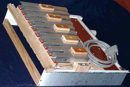
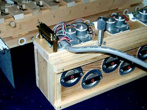
After a number of less successful experimental designs, this Fig 5 shows what I finally arrived at, one that implements some features in a piano, even if certainly not all. In the following enumeration and description of parts, you can locate them with the coordinate grid, drawn in 25 mm (appr. 1 inch) squares.
The pneumatic carrier rail A8-A11, the hammer rail B11, the damper rail D1, and the reinforcement rail A1 bridge the gap between two iron end plates A1-C16 (blue). Front (right) edge of these plates are folded to the sides and hooked with keyholes onto two big screws in two pillars in the organ cabinet. Those same screws similarly carry the sounder rail D6-D8 holding 10 tuning forks located on 40 mm centers. So by loosening the screws you can easily first lift out the sounder rail, and then the entire action, in one piece.
B15-C16 is an electropneumatic rail carrying 10 Reisner chest magnets (OSI #5501.32) and all electrical wiring under a protective cover plate. It also holds the air intake at B17 and is screwed and gasketed to the valve unit A12-C14. This unit is held by two screws A15-16 against the pneumatic rail - loosening those you can take out all valve machinery and leave the mechanics in place.
The pneumatics A6-B10 are held with two M3 machine screws into Tee nuts in the fixed leaves. Each pneumatic has a return staple spring at its hinge A6, and its moving leaf similarly holds the back check and jack bar A4-B9. This bar has a slotted mounting hole for fine positioning the small jack B9-C9, which is hinged to its lower end with soft and thick leather. The jack is held by a spring wire B8-B9 at right angles to the moving lid. The slanted free end of the jack pushes the hammer at a pin C9, (equivalent to the "knuckle" in a piano action) which is fixed crosswise in a hole in the hammer butt C9-C10. The slant on the end of the jack prevents the jack from skidding off the pin as long as it is pressed against it. The hammer pivots around a cloth bushed pin, fixed in the hammer flange C10-C11. This flange also carries a let-off regulation screw that will stop excursion of the pneumatic lid against a pad B10 (red), just before the hammer head A3-C3 reaches the sounder E2-E11. During the final free flight of the hammer, the jack is flipped upwards by its little spring B8-B9, so that when the hammer rebounds from the sounder, the knuckle pin slips down the back of the jack. Then the hammer is free to rebound, but when it is nearly back to its start position it is caught by the upper end of the backcheck block B4-B5. The position of the backcheck block can be adjusted by means of a slotted screw holes where it is fastened to the bar at A4. It must be accurately located such that the backcheck pad doesn't touch the back of the hammer head when the pneumatic is collapsed, but will grab it when the pneumatic is inflated. There are sandpaper washers glued to the pneumatic leaf at B8 and the hammer rail at C11 to prevent the screw joints from slipping.
When the pneumatic returns at end of note, the hammer is released, and comes to rest against the long right side of the backcheck pad. In this position, there is now enough room between the hammer and pneumatic leaf, to allow the spring loaded jack to pop back under the knuckle pin; ready for the next stroke. There is another screw through the moving pneumatic leaf B10 that finely regulates the collapsed position of the pneumatic. The head of that screw is inside the pneumatic and hits against a pad inside, on the stationary pneumatic leaf.
A small peg at the side of the backcheck has a hole and a pad for the damper coupling wire A4-D4. At rest the damper D1-D4 is pressed against the fork tine by a brass leaf spring D1-D2 (left) which is held in place by an excursion limiting screw into the damper rail. Each damper pivots on two little pins driven into the damper rail at top D1. The effective length of the coupling wire is regulated with the loop A4. The right end of the wire forms a hook that cannot escape from the hole in the damper arm D4. That hole, as well as the one in the peg B4, is oblong. When you unscrew the damper rail from the end plates, you can rotate the rail by 90 degrees and easily unhook all the coupling wires.
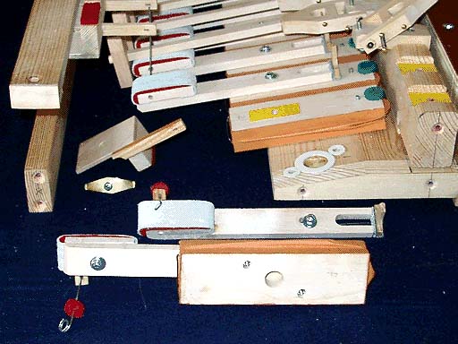
Fig 8. Actions in different stages of assembly, with end plate removed. The yellow patches in the hammer rail grooves and on the pneumatic leaves are glued-on sandpaper. This makes for a firm mount using only one screw.
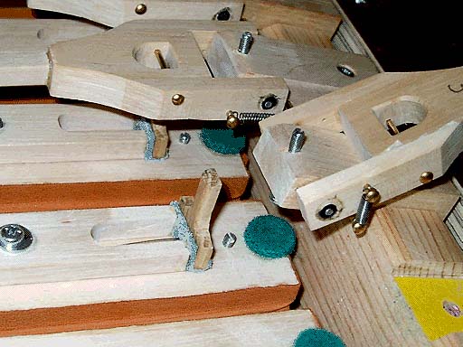
Fig 9. Closeup of the jack mechanism. The little hammer return springs just keep hammers in home position when the harp is mounted upright. They do not appreciably affect the function of the action and allow the hammers to be folded out of way as shown.
Jack escapement. When hand operating the mechanism there are conspicuous high frequency clicks from the jack hitting the hammer butt and drive pin. These are however completely inaudible when playing. A major disturbance instead comes from the corresponding fast force steps transferred to bigger supporting structures that radiate more efficiently, acoustically. The best pads against this appeared to be the thick leather hinge for the jack, B9, and the cloth bushings in the hammer butt, C10. The hammer itself is a very poor sound radiator, it is a lean structure, open at all sides. The pneumatic moving leaf has a big surface, and because its inner side is screened off by the covering it becomes an effective radiator (cf. loudspeaker in a box). The hammer and pneumatic rails form a big, well radiating structure that should be protected from sharp blows.
Pneumatic end stops. Two 9/64" Green Abstract Cloth pads on the pneumatic, B10, one at its moving lid for the let-off screw, one inside for the collapsed positioning screw are of major importance to reduce thumps.
Hammer backcheck. The backcheck block is heavily felt padded and covered with soft leather, dull side out. This reduces the thump when the rebounding hammer is checked. Also, when the pneumatic collapses to release checking, there is a secondary thump as the hammer comes to rest on the side of the check pad.
Damper coupling wire. The pad, A4, damps rattles in the wire and prevents a click from being radiated by the damper when it is pulled away from the sounder.
Valves. The spitting noise pulses from the valves when they switch is decreased when the valve travel/gap is reduced. However, if too small, then airflow to and from the pneumatics is impeded and speed is reduced. Checking with a pressure transducer at the valve output I found the limit to be about 1 mm gap. This noise is not too disturbing as it is natural in any organ pneumatic logic.
Sounder rail. The sounders must be resiliently mounted such that the deliberately hard knock from the hammer is not too much transferred to the cabinet fixed structures. (Compare the piano where the corresponding component is the cast iron plate - because of its heavy mass this does not absorb and re-radiate very much of the hammer blow).
My first type is covered with thin Tyvek ((R) DuPont,
polyolefin
fiber sheet, used e.g. in untearable mail envelopes). Here the folds go
inwards and are stiffened by thin cardboard ribs. The later (and final)
type is covered with pouch leather, without any ribs, such that the
folds
go outwards. Here in fig 10 is a sketch of the rig (part of the actual
machine) to find the static force, finally delivered to the hammer
head.
Fig 10. Sketch of rig for measuring static characteristics of the driving pneumatic and linkage.
With the indicated dimensions the leverage from the center of the pneumatic lid, up to the hammer head is K=(75/50)*(200/25)=12. A calibrated scale stick is placed beside the hammer. Two bias weights eliminate backlash and prevent the mechanism from moving when you switch pressure to the pneumatic on and off. Two measurement series were done. For both, the vertical position X of the head was stepped through different positions along the scale. One measurement was for the 'active' component, the change in force with air drive switching. The other was for the 'passive' forces from stiffness in the pneumatic cover and any return springs. Results are shown in fig 11 as force referred to the pneumatic lid center vs. displacement of that same point from the collapsed state.
Fig 11. Forces from air inflation, pneumatic cover deformation, and return spring vs. displacement, for two different coverings of the pneumatic, sections at right are taken near the opening end. Forces and displacement are referred to the center of the pneumatic lid which is 30*100 mm. The displacement is hammer head X divided by K. Air pressure is 3 kPa (12 inWC), at the present area developing a nominal force of 9 N (appr. 2 lb).
The total force is obtained from the graph as the sum of the return spring and cover deformation components. Then, if air drive is on, you add that component as well. Exercising the two pneumatics in your hand you perceive the Tyvek one as being very stiff compared to the leathered one, much more so than may be obvious from the graph. But, at rest for example, with the actual return spring the Tyvek one will collapse to about 1.4 mm gap while the leather one goes down to about 0.6 mm. When opening wide, the leathered one stops at 8 mm displacement where the leather abruptly goes taut. The Tyvek one can be stretched almost to 10 mm, but only using considerable force.
In the air drive force component there is a prominent difference between the two due to the geometry of the covering. The pressure on the inward folds at small displacements counteract the pressure force operating on the lid, and you reach the nominal force only when it is fully open, slightly beyond 7 mm. Contrarily the inflating outward bulges on the leathered one, at small openings help to give an even bigger force than nominal. The area of the chart below the air drive curves and between the working range displacement lines measure the total energy delivered by the pneumatic. This means the soft leather covered ones have a definite advantage, perhaps 20% more power. There is a further advantage, in that they are very much easier to make and their softness that allows some increase in throw. This is what I finally did in the present design - the hammer shafts were shortened from 200 to 170 mm which then gives a leverage factor about K=10, keeping a X=50 mm hammer head throw. An operational difference, even somewhat better than predicted by eq (6) with modifications in F and K, showed up such that the maximum note repetition rate increased from about 8 to about 10 beats/second. It should be noted that Wurlitzer harp pneumatics were also made with unreinforced pouch leather (outward bulging) covers; even though this configuration goes against the grain, for many organ traditionalists.
After the delay due to the valves the hammer accelerates in a throw parabola to strike at about 55 ms. It appears that the projected 3 m/s incident speed holds, and after the strike the head rebounds with about 1 m/s constant speed toward the backcheck. At its maximum 10/s repetition rate (100 ms intervals) the hammer is never checked, it barely succeeds to have the jack engaged for the next stroke. It is noteworthy that the pneumatic does collapse with a matching speed despite its rather weak return spring, this because of its small inertia combined with sufficiently wide evacuation channels.
For moderate changes in hammer weight (e.g. to 6 or 12 g) the diagram is stretched timewise as suggested by eq. (6), but at no perceptible consequence for the emitted sound level. I also verified the rebound speed does not depend on the material (leather or rubber) in the pad of the hammer striking surface. The hardness of this pad controls the very short contact time and is essential to balance the inharmonic striking clang against the fundamental persisting afterwards. But the energy absorbed in this pad during the strike is negligible.
The pneumatic force driving the hammer head is to the order of ten times bigger than gravitation. This means it is not very significant whether the action is placed horizontally (like in a grand piano) or upright as in the present case, e.g. timing and rebound speed are only marginally affected. However, to ensure the upright hammers to stay in home position at rest they are equipped with return springs.
The valves are conventional outside pouch operated ones. The 10 of them for one half of the harp are staggered in a common unit A12-C14 where a central pressurized box is surrounded by a pouch well board and a valve seat carrying board. Staggering is necessary as the 35 mm well diameter is close to the 40 mm sideways division between mechanisms. This package is held together by a dozen screws. The soft leather pouches are glued to the central box rather than over their wells, otherwise you cannot mount the stiff leather pouch disks on their stems that penetrate the pouches. The Reisner magnets protrude deep enough into the central box that they have to be located slightly off-center from the valves, in order to clear the valve stem wires.
The reaction time of the Reisner magnets is some 15 ms. The secondary valves add more time delay, so that pressure to the pneumatics arrives about 25 ms after the electrical note impulse. Only now you add the flying time of the hammer, which means the note sounds some 55 ms after the electrical command. For a reference we may recall that a quarter note at the common tempo of 120 per minute means 500 ms. The pipes in the organ suffer a similar 25 ms delay for the air pressure, and then there is an additional delay in their tone build-up of similar magnitude for bass pipes. Treble pipes are faster, so in arrangements where the harp plays together with them, it may be a good idea to shift the harp note MIDI commands perhaps a 1/64 note (31 ms) earlier than the matching treble pipe commands.
Fletcher, Neville H. and Rossing, Thomas D.(1991): The Physics of Musical Instruments. Springer, New York. 600 pp. ISBN 0-387-98374-0, ISBN 0-387-94151-7
Rossing, Thomas D. (2000): Science of Percussion Instruments. World Scientific Publishing Co. Pte. Ltd. 208 pp. ISBN 981-02-4158-5.