Theory
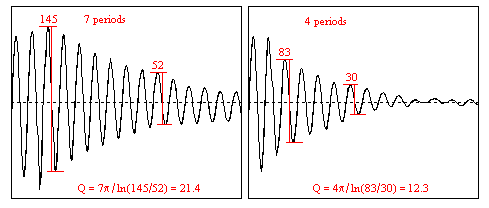
To define a resonator Q value, the archetypal way is to use the oscillating energy stored, divided by the energy lost per radian of the oscillation. There are several equivalent ways, for simplicity more common in engineering. One is to divide the resonator reactance by its series connected loss resistance, the way preferred here, or alternatively a parallel loss resistance divided by the reactance. Elementary concepts relating to Q are outlined by Liljencrants (2002). Equivalent to Q we may use the damping factor d = 1/Q. This is motivated when the damping comes from two or more different mechanisms as in the present case of pipe resonators. We will here derive damping factors for the dominating effects, then add them into a total damping, and finally invert this sum into a resulting total Q value.Here we basically discuss in terms of a quarter wave resonator, closed at one end, of length
 , with a
fundamental resonance frequency f and
sound
speed c.
The results are equally valid for a half wave resonator, twice as long
and open both ends, such that both of the stored energy and the losses
are
doubled. For practical precision measurements a half wave resonator is
preferred since this eliminates possible anomalies in an imperfect
stopper.
, with a
fundamental resonance frequency f and
sound
speed c.
The results are equally valid for a half wave resonator, twice as long
and open both ends, such that both of the stored energy and the losses
are
doubled. For practical precision measurements a half wave resonator is
preferred since this eliminates possible anomalies in an imperfect
stopper. The symbol f , though without a subscript, is not used here as a general frequency variable. Instead it universally denotes the fundamental resonance frequency, thus with a firm coupling to resonator length.
Another concept, used in line theory, handles distributed losses in terms of an attenuation constant a = r/2Z + 2Z/g , where Z is the line impedance, r the series and g the shunt resistances per unit length. Because the L - f coupling defines a length this can be rephrased into a damping factor d = c a / (4 f ).
As a first step we settle the resonator reactance, its acoustical mass times angular frequency. With cross section area and radius
 the effective
acoustical mass is
the effective
acoustical mass is
where
 is the air density.
The
final reduction factor
is the air density.
The
final reduction factor accounts for the
sinusoidal flow/pressure distribution within a pipe resonator, making
its
effective mass less than the total of the tube. Next step is to
evaluate different loss mechanisms.
accounts for the
sinusoidal flow/pressure distribution within a pipe resonator, making
its
effective mass less than the total of the tube. Next step is to
evaluate different loss mechanisms. , in
the baffled case and for
, in
the baffled case and for 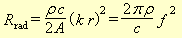

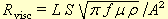 where
where 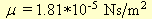 is
the air viscosity,
is
the air viscosity, 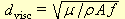
 .
.  graphically shown
in
the following figures.
graphically shown
in
the following figures. 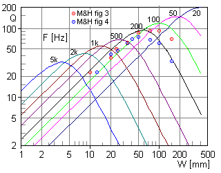
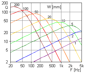
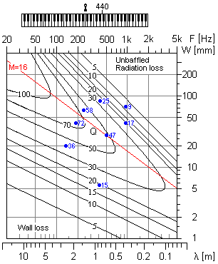
 . The results
conform reasonably well with
the
theory.
. The results
conform reasonably well with
the
theory.
 where
where