Electro-pneumatic valve reaction time

Johan Liljencrants

Repetition rate in the valves for an organ wind chest or for other air driven devices is an issue of interest. This reports some measurements on a few different standard electro-pneumatic devices, in particular how pressure varies with time in their interior structure. Additional examples relate to the ongoing project of restoring the Skandia theatre organ in Stockholm, a Wurlitzer 2/7 style E, opus 1254.

For measurements a controlling electromagnet valve was recurrently driven from a free running multivibrator, delivering a 12 V, 5 Hz square wave that also triggered an oscilloscope. The scope displayed the signal from a semiconductor pressure transducer, connected via probe holes to various parts of the valve under test. In some cases valve motion was recorded using an infrared semiconductor reading fork. The graphs following are tracings from digital photos of the oscilloscope screen. Most measurements were done at an air pressure about 2 kPa (8 inWC).


Chest magnets

The electro-pneumatic interface used in most cases here is 
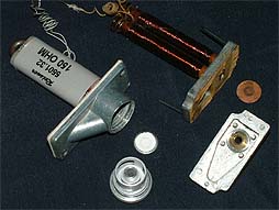
a Reisner chest magnet with 150 Ohms resistance, driven with 12 Volts.

Initially, consider the actions within this device. The first delay component is electrical in nature. When the drive voltage is switched on,  the current and the magnetic force on its armature will grow only gradually toward the stationary values determined by voltage and resistance. This is because of the inertial inductance of the magnet coil. At some point the magnetic force is enough to pull the armature, being a small magnetic disk, against the force developed on it by the air pressure. The disk then flies toward the magnet and the output is switched from chest pressure to atmosphere in another few milliseconds.

When the electrical switch is opened for turn-off the inductance of a bare magnet induces a violent voltage spike that would cause arcing in a mechanical switch, or immediately kill a semiconductor switch. To avoid this it is customary in semiconductor switch designs to install a freewheel diode to limit the voltage excursion to the supply voltage. A consequence of the diode is however that it will take some more time until the energy of the collapsing magnetic field has been dissipated in the coil resistance, such that the valve disk will return.


In view of a surprising inequality between on and off times reported below for a Wurlitzer offset chest, also a classical (1926) Wurlitzer magnet was analyzed. The Reisner (left) and Wurlitzer (right) magnets are shown in this photo with their valves disassembled. They use the same operational principle while they differ in constructional detail. The Reisner pallet is of thin iron sheet with a paper gasket,  the Wurlitzer pallet is thicker and copper plated.


Reisner
Wurlitzer
Unit
Coil resistance
150
175
Ohm
Coil inductance
0.30
0.32
H
Bottom hole diameter 3.9 3.3 mm
Pallet diameter
11.2
11.2
mm
Pallet weight
435
650
mg
Pallet throw
0.84
0.85
mm

In both magnets the bottom seat is on a threaded plug such that pallet throw can be modified away from the factory setting. This setting is close to what is defined in the appendix below as "fully open".


Electrical connection variants

Four different electrical connection principles were tested, as outlined here.

The Mech alternative is what was used in the old times before semiconductors, the switch is a purely mechanical device where the contact points are mostly made of silver. When the switch is opened the voltage across it becomes several times higher than the supply. The magnetic force holding the pallet then disappears instantly.


Diode stands for the inclusion of a freewheel diode to protect a semiconductor switch from over voltage when opening.

Since such a diode will increase turn-off time, a few countermeasure alternatives were added. Zener stands for the inclusion of a 12 V Zener diode such that the voltage across the switch at turn-off is higher than the supply, but now limited to about twice that voltage. Also a functionally equivalent alternative is shown, but this time using a 24V Zener diode connected at a different place.

The final variant examined is Resist where the magnet is series connected with a passive resistor, here arbitrarily selected to have the same resistance as the magnet coil. This requires the supply voltage to be doubled but speeds up the magnetic field collapse at turn-off. An additional merit is that turn-on is also speeded up since initial voltage to the magnet is then doubled.


Operating speed

These graphs show measured turn-on and turn-off times, defined as the time from electrical signal until output pressure, on its way up or down, reaches half the supply pressure. The horizontal axis is for varying the supply pressure from .5 to 5 kPa (2 to 20 inWC).

Turn-on times increase with pressure since the drive current and magnetic force must go higher before the pallet is moved. It is seen that turn-on times are the same for all drive alternatives except Resist where the doubled initial magnet voltage increases speed.

Turn-off times go down with increasing pressure for an analog reason. But a most striking feature is that the electrical connection alternatives gives such a marked difference in turn-off times. This is a memento in restoration work where the original Mech variant might be substituted by the Diode alternative, should a modern solid state relay be installed. This will overthrow an earlier balance between on and off times. While turn-on remains the turn-off times might then increase enough to be musically relevant, notes being slightly prolonged.


A conjecture is that the Wurlitzer magnet has a more efficient magnetic circuit, probably due to its greater pallet thickness. This promotes shorter turn-on time and is good for handling higher air pressures. On the other hand it causes a large asymmetry in on vs. off times. Particularly at low pressures the pallet sticks a rather long time to the magnet, until the magnetic force has declined enough that the air pressure can push the pallet back to its passive position. Probably turn-off time can be shortened by installing a thicker gasket between the magnet and the pallet.


Pallet throw adjustment

The turn-on and -off times of the Reisner magnet were measured at two pressures with Diode drive and varying its easily adjustable pallet throw. The original throw setting 0.84 mm is indicated with a vertical line.

The electric current has essentially stabilized after 30 ms, and if the valve has not switched by then it will never do. At a pressure around 6 kPa (24 inWC) the magnetic force is no more enough to pull the pallet unless the throw is reduced below nominal. Even a small decrease in throw will increase pressure handling capacity a lot, at some sacrifice in flow capacity.

Turn-off times are controlled by pressure (and electrical connection princple) but are rather insensitive to throw.

There is no reason to adjust throw to be greater than the original and optimal 0.84 mm setting since this would increase all times and reduce pressure handling capacity, without improving flow capacity. This Reisner magnet appears to be optimized for somewhat lower pressures than the Wurlitzer, perhaps the range 1 to 3 kPa (4-12 inWC).


Standard 1/2" valve, bellows/pouch actuated

In these valves the outputs connect alternately between ambient and, when activated, the pressure source.


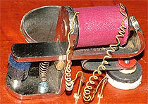
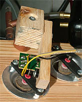
The photo shows a measurement rig for output pressure and valve stem displacement. The valve stem partially interrupts the light path in the infrared LED/sensor reading fork mounted on a small green PC card. Behind the support rig a pressure transducer is connected with a plastic tube to the valve output. The output blows to the exterior through a 10 mm piece of 3 mm i.d.tube constriction. This allows a flow near 0.4 liter/sec at 2 kPa pressure. Such a constriction, essentially smaller than the valve, is necessary for a downstream pressure to build up when the valve opens.  
 

Two valve versions were tried. In one the stem was driven by a small bellows, 1 inch cube, in the other by a 1.5 inch dia. pouch, both covered by thin tan pouch leather. The throw of the stem was about 3 mm, 1/8". The figures below show at left records when magnet current was turned on, middle when turned off. To the right are the general layouts of the valves, shown in the off position where the output pressure is at ambient level.


The red traces show the pressure inside the bellows or pouch cavity and were recorded simultaneously with the output pressure in dark blue. The black displacement was taken in another session, again together with output pressure, this time rendered in light blue. These blue graphs should ideally have been identical. The small fast oscillations (around 700 Hz) slightly obscure what is happening. They are not relevant to the function of the valves but come from uncontrolled acoustical resonances in the cavities, channels and probe tubes.
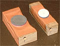
The internal red traces reveal actions in some detail. First look at the left graphs for the turn-on sequence. At time 0 voltage is applied to the magnet and at 7 ms the current has grown enough that the magnet valve begins to open and the red trace begins to drop. At 10 ms the bellows/pouch force has grown such that the upper valve disk is pulled off its seat against the chest pressure and the valve stem moves to its opposite position in the following 3 or 4 ms. That transition flight is somewhat faster in the pouch driven valve, presumably because of its smaller moving mass. During the flight a volume of air has to evacuate through the magnet valve. This volume is greater from the pouch cavity than from the bellows interior, apparent from the different plateaus in (red) pressure from 10 to 14 ms. The armature flight intervals are marked in red at top of the diagrams. At the end of flight the lower valve disk hits its seat to stop the armature, and the blue output pressure is up. Also the bellows/pouch red pressure goes to zero as evacuation stops abruptly, evoking strong transients.

The turn-off sequence graphs in the middle show very similar behavior and timing. The noteworthy thing is the intermediate plateau in the red internal pressure graphs during the valve stem flight from about 11 to 16 ms. In this interval the pressure difference between bellows/pouch interior and the chest drives the airflow to refill the interior.

The difference between the bellows and pouch driven alternatives appears to be insignificant. It is rather up to the designer to select which alternative to use with respect to practical issues like component count and available space.


Puffer actuated valve

The puffer is a rationalized variant of a pouch, where a square piece of leather is wrapped over a sawed out cavity in a wood block. The valve disk is glued to the center of the leather, and inside the puffer a helical spring pushes the disk outward. The disk operates against a tubular seat forming the output. This kind of valve either closes the output or connects to pressure. A less general principle than the previous valve, mainly useful as the note valve for a pipe.

In this case the output seat was a 12/10 mm dia. tube. Two different puffers were compared, one small but adequately sized, and one oversize. Puffer dimensions for the cavity below the leather and pallet diameter is as follows:
Size
L x W (mm)
Throw (mm)
Volume (cm3)
Pallet (mm)
Small
30 x 17
2
1
15
Large
40 x 25
4
4
25


Again the pallet flight intervals are indicated in red at top of the diagrams. There is an obvious decline in operating speed with the oversize puffer as this one contains a greater internal volume of air to be transported during the pallet flight.

At turn off the internal spring is necessary for the pallet to get moving. The small pressure difference across the leather works in the wrong direction and could keep the valve open unless the spring got it started. But when the pallet gets almost closed and the output pressure declines, then the pallet is vigorously slammed against its seat causing the big transients at the output.


Comparable direct action magnet

The direct action magnet of comparable size at hand was made by Laukhuff and has a 75 ohm resistance.

The primary merit of this device is simplicity, a single ready made unit for its function. But its performance is less perfect than the electro pneumatic alternatives above. The electrical power needed to maneuver its coil is significantly higher, and critically dependent of chest pressure. Also its variation of magnetic force vs. position is not optimal, and operation is a bit sluggish because of the weight of the moving armature. Electrical current, displacement and output pressure are seen in the following records:


At turn-on the electrical time constant is short enough, some 5 ms, but the drive current is barely enough such that the armature begins to move at some 13 ms where current has almost reached its stationary value. The pallet flight time, marked in red, is to the order of 10 ms, a rather long time, dictated by the weight of the moving armature. At 30 ms the armature hits and bounces against its blue stop felt pad, visible at left in the photo. The back electromotive force from the movement of the armature is indirectly indicated by a small decline in the current during the 25 to 40 ms range.

At turn off the armature begins to return soon enough, but its flight is rather slow because of the weakness of the return spring. The pallet closes at 15 ms, but the mass of the armature combined with the leaf spring holding the pallet makes the armature bounce such that there is a spurious puff of air released in the 23 to 27 ms interval.


Wurlitzer wind chest


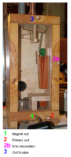
The following measurement was taken on an offset wind chest of a Wurlitzer style E theatre organ, currently in restoration. The magnet and primary valve are similar to the type illustrated above, except the valve disks are differently placed such that the output pressure characteristic is inverted.

The action of this primary system is somewhat slower than those in the example above, one factor is because the bellows are bigger. The measurements below apply to the secondary bellows, operating the top pallet via a lever mechanism.

The displacement of the output pallet was not measured here, but the secondary internal pressure graphs reveal the approximate intervals where the leaf of the secondary moves. These intervals (marked in red at top) are inferred from the plateau with an intermediate pressure. The difference between this intermediate pressure and the final pressure is the driving agent to move an airflow out of the secondary bellows, or into it in the turn-off case.


The pronunced asymmetry between the on and off times suggests that maybe the pallet return spring is weaker than optimal or perhaps that the pallet is opened too far. But later experience showed that the Wurlitzer magnet is also inherently slow at turn off.


In the restoration of the Wurlitzer main windchest a one-note replica with dimensions as for its smaller pipes was built, photo at right. Behind its plexiglas front you can see its components moving. A number of probe holes were drilled into the channels for connection to the pressure transducer. Probe hole number 1 is at the output of the magnet valve, number 2 at the output of the primary valve. An extra hole 2b was put close to the entry of the secondary bellows, at the opposite end of the primary-to-secondary channel, going up inside the right wall. Number 3 is above the note pallet to check the pressure reaching the pipe.

Air was supplied from a speed controlled shop vac connecting through a round hole in the back wall. Due to the rather long and narrow connecting hose the air supply suffered some slow variations, perhaps +/-10%, obvious in the records below at places where pressures should have been steady on the nominal value.

The secondary bellows is of the smallest kind in the organ, with 22 x 90 mm leaves, covered with relatively thick pouch leather, about 0.5 mm. When the pallet barely opens the original pallet springs deliver a force about 0.3 N (30 grams, 1 oz), referred to the end of the pallet spoke, where it rests against the secondary bellows felt pad. In this replica a slightly stronger spring was used, giving about 0.4 N.

Below are two complete measurement sequences. The first one used a Reisner magnet and was run with 2 kPa (8 inWC) pressure. The second run was at 5 kPa (20 inWC) pressure and used a Wurlitzer magnet. This selection of magnet vs. pressure tends to minimize the timing difference between the records.


The Reisner magnet at 2 kPa. The small green and blue marks show the time-wise translation of the patterns at 5 kPa.


The Wurlitzer magnet at 5 kPa. The small green and blue marks show the time-wise translation of the patterns at 2 kPa.

Some identifiable events are marked with letters in these diagrams:
a: The magnet pallet has opened and the primary bellows begins to evacuate.
b: The primary valve armature hits the upper seat and primary evacuation stops suddenly giving a negative pulse in the green trace. Meanwhile the secondary bellows has begun to develop a force on the main pallet, but is not yet moving.
c: The force from the secondary bellows has built up enough to tear the main pallet open against pressure, blue output pressure starts to rise. Once this happens the force from the secondary drops momentarily, to tension only the pallet spring. The secondary starts moving with a jerk and a corresponding puff of air gives a positive pulse in the violet trace. This signifies the acceleration of the air in the channel. There is little seen of it at test point 2 (red) close to the vented end.
d: The main pallet is fully open and secondary bellows motion is stopped against the felt rail. The abrupt stopping of the secondary evacuation flow gives a negative pulse in the violet trace. The extra pulse in the Wurlitzer trace at 31 ms suggests that the bellows and pallet spoke return once more against the stopping rail after a bounce.
e: The magnet pallet reaches home position and the primary bellows begins to refill and its armature moves back down.
f: The primary armature slams shut. Secondary bellows refill has already been started mildly, but now proceeds at full speed under control of the pallet spring force.
g: The main pallet is slammed shut and the secondary motion stops. From now no air is consumed, so the inertia of former flow in the supply hose induces a slow rise into overpressure.


These cases combined suggest the following conclusions about the time delay from electrical signal to operation of the note pallet. This delay can be divided into two main components:
1. A first delay is set by the magnet and depends on the magnet design, the air pressure, and the electrical drive circuit, as discussed previously above.
2. A second part is the additional delay in the bellows/pallet mechanics.
2a. At turn-on these elements are driven by the air pressure. It appears that operating speed is then about proportional to the square root of pressure implying that the Bernoulli law is important, the one that relates pressure drop to linear air speed in the channels.
2b. At turn-off the elements are driven by the pallet return spring and pressure is of no consequence for the operating speed. For fast turn-off the the return spring should be tuned to be as strong as possible with respect to the pressure, such that turn-on is not jeopardized.
To promote operating speed under both of points 2 a general measure would be to allow a generous diameter in the connecting channels, keeping linear air speed down.


Wurlitzer action less primary valves

It has been suggested one might do away with the primary amplifier valve in the Wurlitzer action, and bypass it by a slight modification as shown in this figure.

The question is then to what extent this would affect the timing. Perhaps action would be slowed down, and to counter act one might then possibly increase the diameter of the magnet valve outlet.

This variant was tried in the one-note replica shown above, with no such change in the magnet, and gave the following results, the magnet driven in the 'diode' mode:
 
 
Again the blue traces are for the output pressure reaching the pipe, the red ones the internal pressure of the secondary (now only) bellows. The bars at top indicate the time intervals the bellows is contracting and expanding.

It appears that turn-on time is insignificantly changed. The air passage to evacuate the bellows is now more narrow, but any consequent slowdown is compensated as there is one less stage of valves in the action chain. One should however note that the bellows must be in good shape with a small air leakage. This is not as important when you have a primary valve presenting a larger area to evacuate it at turn-on.


Again turn-off is somewhat slow. Partly this is due to the 'diode' type of magnet drive, slowing it as outlined above.The other reason is that turn-off refill speed of the bellows is governed by the pallet return spring and the channel area, not the blowing pressure. But it is hardly practical to increase the magnet air passage area from chest to magnet control output.

To conclude it seems practical to omit the primary valve as long as the (formerly) secondary bellows is in good shape. The little increase in turn-off time is not very significant. This time may be shortened by increasing the tension of the pallet return spring, but  this would decrease the margin that the bellows can develop enough force to open the pallet at turn-on.


Appendix: Necessary throw for a fully open pallet

Here are two rules of thumb for what is the necessary pallet throw to make a valve fully open. One case is for a circular valve seat of a specified opening diameter D, where the pallet is a disk, essentially moved axially. The other case is when the seat is a narrow slot where the pallet is hinged at one end, a common design for the pipe valves in a windchest.


Stylized cutaway views of a circular and a slot valve, illustrating the concept of 'fully open'.


The area opened up by the activated pallet is marked in green in these sketches. This is compared to the nominal area of the valve, here marked in red, as given by the seat diameter, or by length times width for a slot.  The definition of a fully open state of the valve is taken that the 'green' and 'red' areas are the same. From that and simple geometric calculus (forgetting about a narrow end section for the slot pallet) these elementary rules follow:

A circular valve is fully open when the disk is moved one quarter of the seat opening diameter.

A slot valve is fully open when the free pallet end is moved as much as the width of the slot.

If the pallet is opened less than these rules prescribe, then there will be an obstruction to the flow, potentially causing an undesired pressure drop. In many cases this is insignificant, since the valve seat may be over dimensioned for reasons of conservation or size standardization. Furthermore, there is no merit in opening the valves more than these rules suggest. Rather a loss, as this would increase the time taken for opening and closure.


2007-11-14, expanded 2008-03-16, 2008-10-13