A Wurlitzer regulator
| An organ air pressure regulator is described, with special regard to the
design in
Wurlitzer organs.
An attached
special purpose Windows PC program simulates its acoustical network. Here several design and
adjustment parameters can be interactively manipulated,
leading to detailed computed pressures and airflows
throughout the system. This may be an aid to understand
and master a regulator installation. You can also study
dynamic effects when drawing a pulsating flow from the
regulator output. This article is a complement to one about Simulation of an Air Dump Ttremulant [1]. Refer to that place for a closer overview of the technicalities of simulation. Further information, particularly on the characteristic of pressure vs. bellows lid lift is found in an article on Setting up a Wurlitzer Regulator Bellows [2]. IntroductionThe purpose of the regulators in a pipe organ is to keep a constant pressure supply to the wind chests, irrespective of what air flow is demanded. This demand depends of the number of simultaneously speaking pipes and whether a tremulant is used.Key issues with a regulator is its stability, how to load its bellows lid, and what may be the influence of connecting trunks. The present simulation may be a support, both in planning and maintenance work. |
A Wurlitzer regulator |
|
|
|
|
|
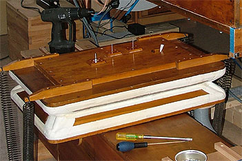
| Fig 1. A small Wurlitzer regulator residing on
its supply trunk. From the lid protrude
three steering
pins for the
internal bars that sequentially push open the control
valves when the lid lowers. |
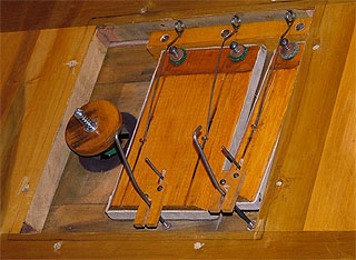
Fig 2. The trio of valves at the bottom of the regulator. |
| The regulator bellows is
built between two lids, connected with inward folded ribs
along their circumference. The ribs are hinged with linen
strips to take up the forces from the enclosed air. These
hinges are hidden under the soft leather strips going all
around to make the bellows airtight. Leather gussets join
the ribs at the corners, and these have a comparatively
large unsupported areas that vary in size depending on lid
lift. The rounding of the lid corners is a characteristic
Wurlitzer feature. The set of springs compressing the bellows and the lid area determine the internal pressure. The bellows loaded this way constitutes the regulator sensing element and also works as a limited reservoir of air. The bellows rides on the air supply trunk, and the interface toward the bellows is a set of valves of unique Wurlitzer design, the 'air control board' in their terminology. As air is consumed from the bellows and its lid sinks, then initially a small 'cone' valve opens a relatively narrow passage to refill from the supply trunk. At lower lid levels first a narrow, then a wide pallet open a progressively wider area for air supply to enter. The three valves have control bars of different lengths to make up for a smooth, non linear characteristic of total valve open area vs. lid lift. This design is rather complicated, both to build and to inspect and maintain. Its internal parts are difficult to reach, and its externally protruding steering pins are easily bent. But the gradual and progressive valve opening are quite efficient features to make the regulator stable. In the same time it obviates a need to relieve the pallets from input pressure pulses when they close, something that could otherwise even end with a latch up. In other regulator makes one would normally avoid this risk by using a different valve type. One where the input pressure does not transform any of the input pressure into a force to operate the valve, e.g. a slider, a butterfly, or a curtain valve. |
| For simulation of the
regulator an analog network was developed as in fig. 3. Blue
symbols indicate pressures at nodes, and red symbols are for
flows in branches. The analog diagram uses symbols borrowed from electrical technology, though all its elements in our case are acoustical. The purpose of the diagram is to formalize which ways the different airflows U will take, and to visualize how you can compute partial pressure differences from the flows passing the various impedance elements, denoted in black. The basic principle is to apply Ohm's law in acoustical terms, that Pressure = Flow*Impedance. Further technical detail is developed in the trem article [1]. All is driven from a fan by the pressure Pf which is taken to be constant. Its airflow Uf is fed by a trunk where its length and diameter define the elements Rf , Mf , and Cu. Pu is the pressure entering the regulator input. Here the resistor Rr represents the valve that is controlled by the bellows lid elevation and allows the flow Ur to enter the bellows interior. Uv is a minor flow taken to compress the bellows volume of air in case its internal pressure Po should vary. The most important elements are Ml for the inertia of the bellows lid and Cl. Cl is a dual element that on one hand represents a next to infinite compliance that is determined by the bellows fold geometry. On the other hand it also generates a static pressure Pl governed by its loading from springs and weights. |
|
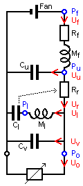 Fig 3. Analog acoustical circuit for a regulator. |
| The
purpose of the simulation is to show the inner workings of
the regulator, and what happens to delivered output pressure
Po when
the load flow Uo
is varied. The design aspect is covered by several
parameters describing the dimensions of the regulator and
its feed. To show consequences of the dimensions you
prescribe a load flow Uo
. This flow is thus an input datum to the simulation, not a
computed result. |
||
Simulation programThe attached Windows PC simulation program (regsim.exe) was written in Borland Delphi Pascal. It presents a screen with numerous scrollbars at the left side, where you can input physical dimensions. With radio buttons you can select whether to see these inputs in SI units or in traditional US, but computations and result reports are done in SI throughout. In the middle of the screen fig. 3 is reproduced as an orientation aid. It is supplemented with resulting values of those impedance elements that are constant, essentially the masses and compliances. The resistance elements vary nonlinearly with flows throughout the simulation. At top is an image area to show results as graphs vs. time for the various pressures and flows. Here the zero line and scale can be adjusted with scrollbars. Check boxes at right are used to select which data to display.The simulation time span covers 1.5 seconds, schematically divided into three equal intervals with different loads. The first is when the regulator is charged by a surge of air from initial rest to a fully inflated state. In the second interval a constant flow Uoo is drawn, with magnitude as set from the scrollbar. The final interval is relevant to a system where an air dump tremulant is operating. The load is then additionally superimposed with a sinusoidally varying component of amplitude Uoa , oscillating at freqency fo. The reader is encouraged to run the program and to modify conditions at will. Looking at the various result graphs should help to familiarize with the regulator function and with consequences of dimension changes. |
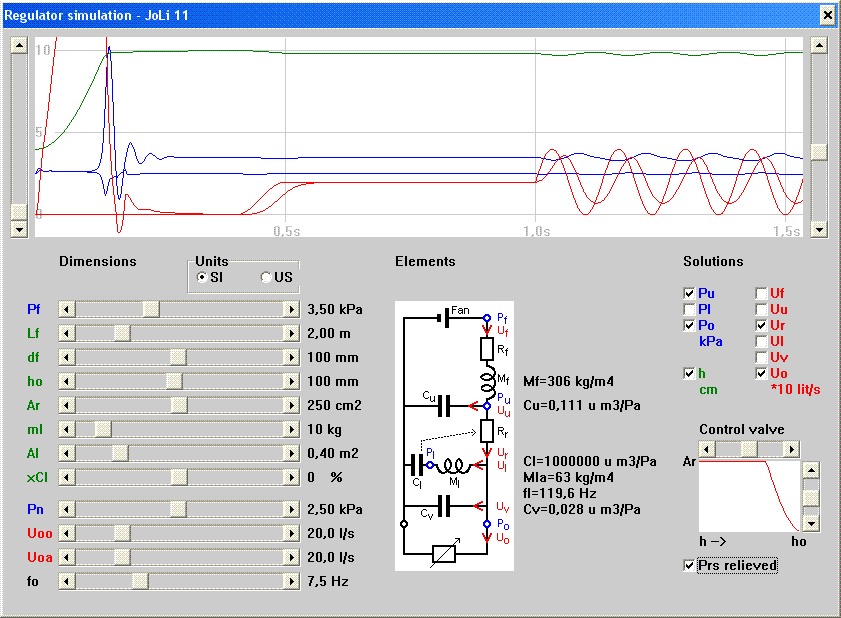
| Fig. 4. The regsim.exe screen
with default input parameters. The regulator bellows is
first charged by a big pulse in Ur. When the lid is up at 0.2
sec and the valve closes there is a pulse in input
pressure Pu from the hydraulic hammer effect in the supply
trunk. After 0.4 sec the loading Uo begins to rise and slightly
later Ur rises to refill. At 1.0 sec tremulant load
starts, as set by Uoa. This has a relatively minor
effect on Po since the wiggling lid is light. There is bigger
variation in input Pu due to the inertia in the
feeder trunk. |
|
 |
| Further
comments on the parameters that are input with the left set
of scrollbars. The lowest parameters Uo and fo define the load to the regulator. The average load flow Uoo is stereotypically set into a pattern of zero flow for the first 0.4 sec, then in the next 0.1 sec increasing by a cosinusoidal arc smoothly to the value set by the scrollbar. In the final part the prescribed load may be set to oscillate at freqency fo around this average with the amplitude Uoa. When these parameters are set above zero the simulation shows what happens with a pulsating load, like when a tremulant is connected. Pf is the driving fan pressure. The simulation start is unrealistic to the extent that this pressure is applied momentarily. In a real situation the initial phase would be rather long while the fan accelerates from standstill. For the regulator to work Pf must exceed the regulated output, required to nominally be Pn . Lf and df are the length and the diameter of the feeding trunk. At the end of the charging phase, when the lid goes up and the valve shuts there is a pulse in Pu from the hydraulic hammer effect in the feeder trunk. This effect is much less pronounced using a progressive valve. |
||
| ho is the maximum bellows lid
lift and Ar
is the maximum open area of the control valve(s). To
reasonably approximate a Wurlitzer control board you can
select a 'progressive' model using scrollbars at lower right
beside a sketch of the current model in a small insert
figure. At the top of this you can set the lid height where
the valve becomes fully open. The use of a progressive
characteristic in the control valve is a very significant
feature to keep the regulator stable. With a linear
characteristic as that of a single pallet valve there will
be strong transients as the valve slams shut when the lid
reaches is top position. Such transients are not accurately
rendered because they are very fast and because the
model does not include such detail features as pallet bounce
and elasticity in various structures. |
||
| The
lift at start of simulation is assumed to be 0.4ho . The
bellows can normally not collapse more than this due to the
thickness of the folding ribs. In Wurlitzer regulators such
minimum lift is enforced by stop blocks. The precise value
of this minimum lift relative to the nominal ho has too
little influence on the simulation to warrant a separate
setting option. In a nearby checkbox you can select the regulator valve to be 'pressure relieved', meaning that the input pressure is not allowed to execute a force toward closure of the pallet, another candidate to cause instability. When demand goes down, there will be a pressure surge at the regulator input. Via the pallet control bar this tends to lift the lid, counteract the lid springs, and somewhat lower the regulated pressure. Also there is a danger the pallet is inadvertently held closed by such a surge. The Wurlitzer design with three different size valves is one way to circumvent this problem. Other means is to use differing kinds of valves. An elegant variation, used by Aeolian, is that the pallet upstream side is covered by a relief bellows of same area as the pallet. This bellows is vented to atmosphere, such that input pressure executes no force on the pallet. |
||
| ml is the
mechanical mass of the bellows lid, and Al is the
lid area. These together with the desired nominal Pn
indirectly define a required spring force working to
compress the bellows. Now there is an additional
complication in that the bellows geometry puts a
requirement also on the spring constant. For an inward
folded bellows the spring force should increase with lift in
a controlled way. For constant pressure it is thus not
enough with a certain force at a specific lift, but also the
spring stiffness should be right. Details on this are
elaborated in the separate bellows article
[2]. xCl
is a special parameter to describe how well such spring
tuning has been done, 0% is the ideal. It describes the
percentage shift in pressure Pl as lid lift goes from zero
to ho .
If the regulator springs are too stiff, such that pressure
increases with lift, this is then modeled with a positive xCl . In a
reservoir one can fine adjust this parameter by balancing
between spring force and ballast weights on the lid. When
the lid force is dominantly given by weights rather than
springs xCl
can take a negative value. This results in a negative value
for the bellows compliance Cl which is physically
reasonable, it just means that pressure would decrease when
you inject a volume of air. Lid weight Ml may affect stability as a big lid inertia tends to belate and overshoot the regulating valve. This weight is also the dominant reason for output pressure Po to vary at transient loads Uo. That effect to swamp the regulation is often used as a means to tune pressure modulation depth when an air dump tremulant is connected. As detailed in the tremulant article [1] this is generally an expensive way, since the same effect can be reached by just making the trunk from regulator to pipe chest slightly longer. As a side note the bellows resonance frequency fb is shown, defined by Ml and Cv. This is the frequency the lid will oscillate when you hit it with a stroke. It is a measure of how fast the regulator will adapt to a load change. This frequency should be considerably higher than the tremulation rate in case a trem unit is connected. By elevating the fo parameter one may judge whether the bellows resonance might cause stability problems. Disclaimer: The results of this simulation are believed to be reasonably accurate in quantity, but cannot be guaranteed. In assessing element values for the simulation, the formulas used are in their most basic form, taken from the classical literature. The discrete time simulation method in itself is approximate, and there is some risk from mistakes by the author. |
||
Simulation technical proceduresThe following technical detail only mentions issues special to this regulator simulation, while more comprehensive details are given in the companion tremulant article [1].Initially at time zero all variables are known, pressures either Pf or zero, all flows are zero. From all the known elements and variables an equation system is set up, using the Kirchhoff laws: - For each branch in the network, the motive pressure equals the sum of flows times impedances. - For each node the sum of entering flows is zero. This rendered a system of 8 equations for 3 unknown pressures P and 5 flows U, illustrated in Tab.1 below. The equation system is solved using a standard Gauss-Jordan algorithm. From that all the variables become known, valid for a new time, one interval τ later. Having come that far all resistances R are re-computed, based on results from the previous step, now labelled P and U . This cycle of setting up the equation coefficients and solving is iterated, keeping record of the solutions for display afterwards. When any of the input parameters is changed, the program runs 768 iteration cycles with τ = 0.002 sec to cover the waveform development from start to just over 1.5 seconds. Such an entire round is computed in a small fraction of a second. |
| Eq |
Unknowns |
Knowns |
|||||||
| # |
*Pu | *Pl | *Po |
*Uf |
*Uu |
*Ur |
*Ul |
*Uv | = |
| 1 |
+1 |
Mf/τ+Rf | Pf+MfUf/τ | ||||||
| 2 |
-1 |
+1 | Rr | 0 |
|||||
| 3 |
-1 |
τ/Cu | -Pu | ||||||
| 4 |
+1 |
-1 | Ml/τ | MlUl/τ | |||||
| 5 |
-1 | |
τ/Cv | -Po |
|||||
| 6 |
-1 | +1 | +1 | 0 |
|||||
| 7 |
+1 |
-1 |
-1 |
Uo | |||||
| 8 |
+1 | -τ/Cl | Pl | ||||||
| Tab. 1. The eight network equations used in the
simulation, displayed in a matrix way, such that they are
arranged for the solution algorithm, with unkown and known
variables sorted each side of the equals sign. Clarifying examples:
Fully written out eq #2 would read - Pu + Po + Rr*Ur = 0. That branch equation is easier to understand in the form Pu - Po = Rr*Ur Similarly eq #1 would read Pu + (Mf/τ+Rf)*Uf = Pf+MfUf/τ, rearranged from Pf - Pu = Rf*Uf + Mf*(Uf - Uf )/τ . Here the last term represents (mass) * (time derivative of flow). |
| Ideally, when the
spring/weight tuning parameter xCl is zero, then Pl is
independent of lift and equals the prescribed nominal
regulator output pressure Pn.
However, Pl
is adjusted for each time step with regard to xCl and the
current lift h.
This lift in turn is found from the time integral of
the flow Ul
filling the bellows. Thus Pl
is generally a known input variable to each simulation step
and it may seem peculiar to use it for an unknown in eq #8
of Tab 1. The resulting difference in Pl is used
as a correction though this normally becomes infinitesimally
small because Cl
is so large. |
Related articles |
||
| [1]
|
http://www.fonema.se/tremsim/tremsim.html
|
Simulation of an air dump tremulant Also contains a closer view of the technicalities of simulation |
| [2] | http://www.fonema.se/wreg/wreg.html | Setting up a Wurlitzer regulator bellows On the characteristic of pressure vs. bellows lid lift |
| [3] | http://www.mmdigest.com/Gallery/Tech/airbounc.htm http://www.fonema.se/airbounc/airbounc.htm |
Pushing and bouncing air General essay on the dynamics of organ air supply |
| [4] | http://www.mmdigest.com/Gallery/Tech/tremreg.htm http://www.fonema.se/tremreg/tremreg.htm |
Organ Pressure Regulator and Tremulant
A regulator design and a novel way to tremulate |
Simulator programs |
||
| [5] | http://www.fonema.se/regsim/regsim.exe | The simulator this article is about |
| [6] | http://www.fonema.se/tremsim/tremsim.exe | Tremulant simulator |
| 2009-04-05, rev 2011-10-24 |